
Rigid-Flex Printed Circuit Board
A rigid-flex printed circuit board (PCB) is a multilayer PCB with both stiff and flexible sections. It is used in many electronic devices and systems, from small consumer products to sophisticated military/defense systems that require bending and twisting. Rigid-flex PCBs are a little more expensive than standard rigid PCBs because of the additional layers of materials they contain, but the extra cost is worth it for a number of reasons.
First, the base material of the rigid-flex printed circuit board must be cleaned to prepare it for the fabrication process. This preparation consists of applying a light-sensitive etch resist to the film surfaces and then using stencil patterns to expose certain parts of the surface to light. This exposes the areas that will be etched away to reveal copper traces, which will become the circuit’s patterns. Next, copper foil is added to the etch resist. This copper foil is offered in either electro-deposited or rolled forms and it can be in various thicknesses and weights. It is also typically coated with anti-tarnish or an adhesive-less coating to reduce degradation and protect it from oxidation.
After adding the copper layer, holes called vias are drilled through the layers to be used as the conductor paths that will connect all of the layers together. These holes are then plated with copper to keep the electrical connections relevant through the PCB’s entire design. The flex and rigid sections are then bonded to each other using a mix of heat and pressure. Once bonded, the entire assembly is put through a curing process to ensure that it is fully functional and durable.
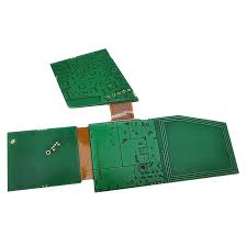
How is a Rigid-Flex Printed Circuit Board Assembled?
For a successful rigid-flex PCB, it is important to use the right materials for both the flexible and the rigid sections. Rigid sections of the PCB should be made from a common rigid PCB laminate such as FR4, while the flexible section will use a polyimide base for its flexibility and thermal stability. In addition, a hatched pattern should be used for the copper plating on the flex section to give it more flexibility and better mechanical performance.
Another tip for a successful rigid-flex PCB is to have the correct bending radius for the expected bending of the flex section of the board. A bending radius of at least 2 times the thickness of the trace will allow it to be bended without cracking. Also, it is advisable to avoid the use of straight or 90 degree copper edges as they will have lower shear resistance than rounded edges.
Once the board is completed, it will undergo reflow soldering to make sure that all of the components are properly glued and connected to it. This involves pre-heating the components and then melting the solder on them in a heated oven. The reflow process will help to create strong solder joints, which will allow the flex-rigid PCB to be bent and twisted without affecting its function or safety. Lastly, the finished product is put through an electrical test to ensure that it functions properly.